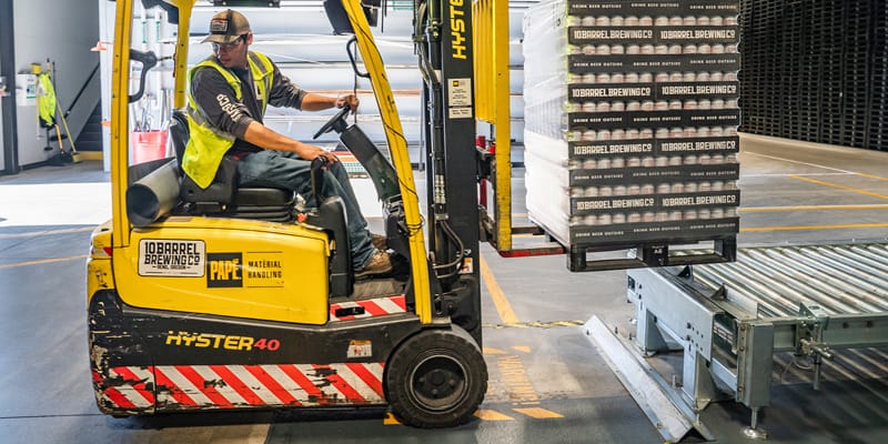
We have already summarized saving capabilities of OrthoGraph in an earlier article , let’s see how we can utilize the same BIM model we have used for facility management, now for production line and most kinds of industrial maintenance, and how it can minimize or avoid breakdowns.
A common mistake while documenting production lines, using the fancy, precise, but confusingly detailed and cumbersome point-clouds. We suggest another approach. Adopting OrthoGraph’s methodology you can capture a BIM documentation containing exclusively the necessary details and properties, using inexpensive devices and all this even quicker.
The best is, that after any change made in the machinery setup it can easily be updated within minutes even by the factory’s own maintenance crew, and the refreshed model can instantly be used in all connected systems thanks to the available integrations.
It is essential in the OrthoGraph ecosystem that the same central BIM model serves all connected systems. In other words, all different divisions of the company can benefit from one building survey. This not only saves from survey buildings repeatedly with only slightly different approach and content, but also ensures the most recent up-to-date data source for the most informed decisions in all areas at once.
Let’s unfold how OrthoGraph supports operation and maintenance processes at production lines:

Shorter maintenance processes
Find the right place – take the right parts and tools with
At a breakdown or scheduled maintenance tasks, the maintenance point, or the device, can be sent to the maintainer as a simple reference link. This can be done automatically from the FM system as part of the workorder if the right integration is in place.
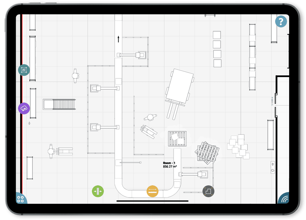
Tapping on the link the maintainer gets an up-to-date floor plan, which he can check in a browser, or with OrthoGraph on a smart device. The maintenance point is automatically selected and shown, either in 2D or in 3D view.
Logged in with the proper authorization before going to the site the maintainer can check the properties and the data sheet of the given device, the attached videos, photos and even more: also other important data available through integration. Based on these data the proper tools and parts can be carried to the site, preventing at least one unnecessary site visit.

Faster repairs
All data about the device is also available on site. Scanning (if available barcode or RFID) or typing the identifier of the equipment brings up its property sheet, with all data. This helps in two ways:
- It is ensured that the job is started at the right place and at the right device,
- All possibly necessary data is available on-site for completing the job.
This latter not only means the property sheet of the equipment, but if the system is set up elaborately, even instruction videos or exploded view diagrams can be included.
If the FM system is available from the site, even the maintenance history and attached workorders can be connected and reached form here, so the real reaction time and repair time can be registered. This is not only helps to complete the job faster, but also makes it easier to follow and fulfill the SLA.

Building the database organically
When the work is done, it must be registered on site. This has further gains:
- Real, precise data can be recorded, data, photos, videos or voice recordings.
- It automatically ensures that the database is kept updated, so the BIM model will be as close to the real world as possible
- Maintenance points left out at the initial survey (either deliberately or mistaken) will also be enlisted in the system with fresh, real data.
This also makes it possible to build the model in more phases, and at the initial survey only gathering the data which is inevitably necessary might be enough. Later with the above workflow will let the missing data migrated into the BIM model also seamlessly using own crew with little or no extra work, time or cost.
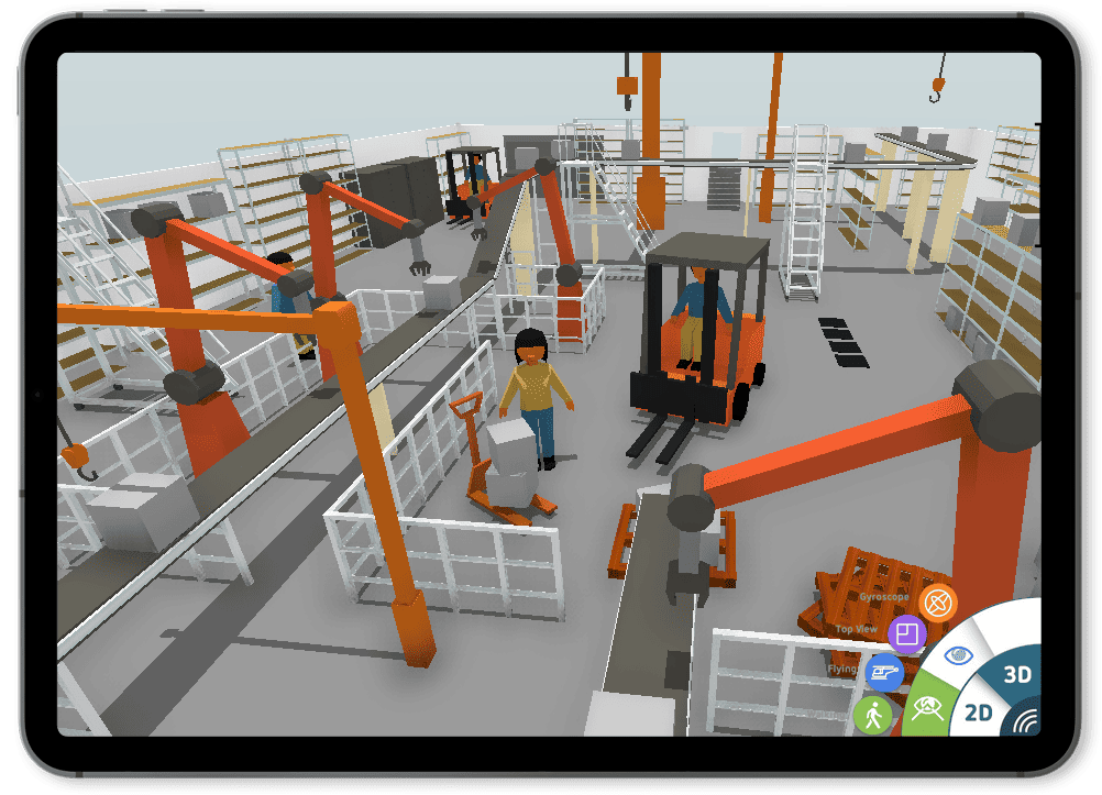
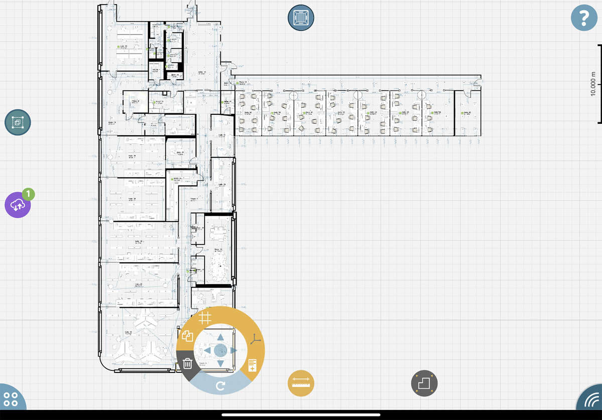
Selecting object on iPad

Instant data visualization
A typical production line or other machinery systems have many measuring or intervention points. Today these can be shown with text description or schematic diagrams, but the real physical location is barely documented. With OrthoGraph all of these POI-s can be recorded, even millimeter-precise (still with the same “cheap” laser distance meters). With system integration these points can be attached to their counterpart in the machine control system, and from that system it is easy to visualize and find the real position of the given part, switch or sensor.
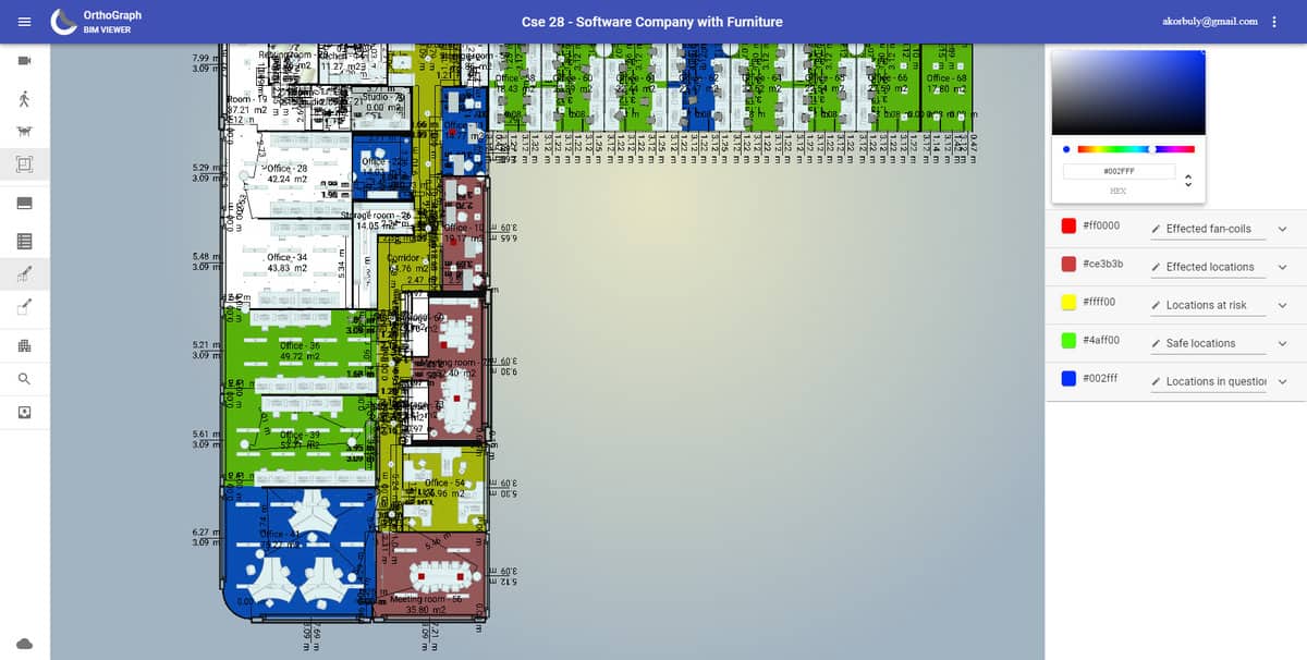
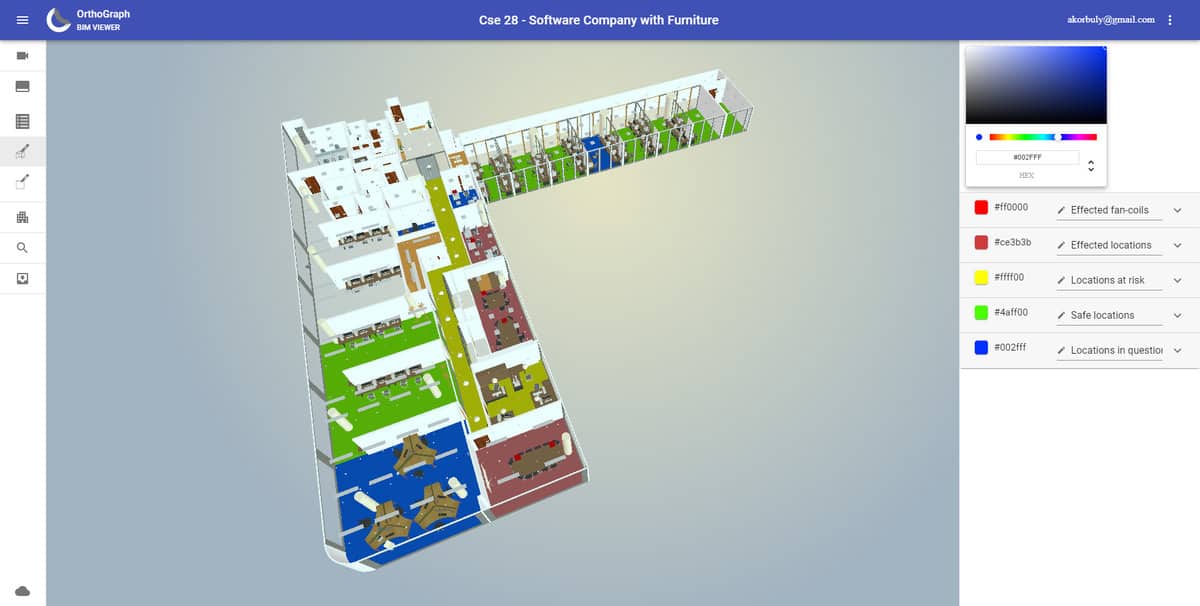
Even more is available: if we want to see more complex models, and the possible connections are predefined, than the consequences of a failed part (e.g. filter, an air handling unit, a valve or a pipe section) can be easily visualized with OrthoGraph in 2D or 3D with color coding the affected areas, equipment. These functions can radically speed up decision making and reaction time, thereby reducing loss and probably even preventing breakdowns.
2D-3D fan-coil problem in browser view

Risk reduction with centralized inventory
The biggest earning of a consolidated database is the significant risk avoidance. If all the maintenance-related data is available centralized, with a system controlled by the building/plant owner, they can be independent from the actual maintenance personnel or subcontractor. All necessary data for the quality maintenance work are available independently from who we are assigning the task.

Tracking changes, rearrangement, reconstruction
Production lines are subject of frequent changes, so the arrangement of the sensors or switches or important parts are also to be updated regularly. Following these is usually a heavy work and big cost, requires educated associates. Not with OrthoGraph: even the crew making the arrangement or the maintenance can update the positions of the machinery and the POI-s using laser distance meters and 3D measuring stations, in minutes.
Please note that in OrthoGraph the representation of the machinery parts is not a 1:1 model like in point clouds from a 3D laser scanner, but a simplified model which contains all necessary information. This makes the model easily updatable by the normal crew operating and maintaining them, with simple and durable devices. As to all equipment, part, measuring point, a property sheet is assigned, where any necessary info, including photo or video documentation, voice recording, external link can be attached, it is ensured that based on this BIM model all decision, work planning, preparation for maintenance or repair will be effective and efficient.
We believe in the “good enough – but simple as possible” rule, instead of extensive but hard to handle and far more expensive to operate solutions. This results in a sustainable documentation and effective operation.
Recent Comments